Quick giveaways
Let's start with some quick giveaways right away. If you are interested, you can find more detailed explanations further down in this article.
Use aluminium anodes instead of zinc
Stop using zinc anodes, but use aluminium anodes from now on. Almost all anodes are these days also available in aluminium. Aluminium offers so many advantages that the only reason zinc anodes still exists is because of habit. After all, many people refer to anodes as "zincs". The less informed people still buy the zincs, but the people who know this secret buy aluminium anodes. The advantages:
Use a central anode
On non-conducting ships, electrically bond all metal objects together and use a big central anode to protect everything. The advantages:
- Your special (expensive) anodes for saildrives etc last proportionally longer if the central anode is bigger
- All metal objects that have no anodes (like rudder shafts) will now be protected
- Less risk of stray voltages because they will be short circuited to the central anode
There is one danger here: If you fail to replace the anode when it is due, or loose the electrical connection to it, one of your bonded objects starts to act as replacement anode. This might be just as well your rudder shaft. So keep an eye on your central anode! Don't let this scare you away though, it might still be a good idea to connect the rudder shaft to a central anode, as will be explained further down.
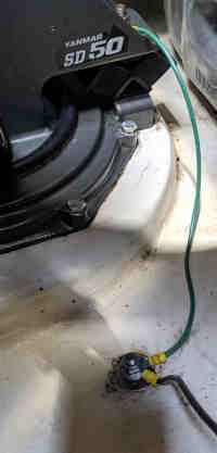
Do not connect the minus of your alternator to the engine block
You should always use a dedicated minus cable from your alternator to the battery bank. Most likely this is not the case, if so, change it right away. If (one of) your saildrive(s) is oxidating and/or consuming its anode very fast (or faster than the other one if you have a multihull), or the metal hull around the engine is oxidating, stray voltage is the culprit. Even if you have no problems now, you will get a (serious) problem when the connection of the minus cable of your engine becomes corroded in the future.
Isolate your anchor winch from the minus and/or metal hull
If your anchor winch is somehow connected to the minus or metal hull, the chain will be connected to it as well. This can have various undesired effects: the zinc layer on the chain will now not only protect the chain but also act as a sacrificial anode for the rest of the ship. If there is some stray voltage on the minus cable of the anchor winch, the voltage of the chain will be higher than the rest of the ship and again it will now act as a sacrificial anode to the rest of the ship.
Do not use the minus cable of the anchor winch for anything else than powering the winch
I know, this big minus cable running all the way to the bow is very handy to use as a minus cable for whatever equipment is located nearby. But all cables have some resistance (losses) and any voltage loss over the cable might present itself as a voltage difference between the anchor winch (and chain!) and the rest of the ship, again inciting unintended impressed current cathodic protection of the wrong parts at the cost of precious other parts.
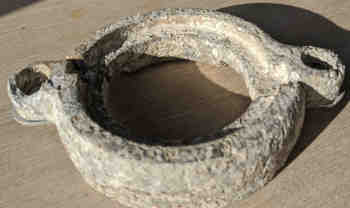
Protect galvanisation layers with aluminium anodes
Galvanisation is often used to protect mild steel, like anchors and their chains, and it is achieved by chemically bonding a small zinc layer over the steel. The zinc works like a sacrificial anode and protects the steel underneath, but unfortunately after a while the sacrificial zinc layer will disappear and the rusting begins. Since aluminium is a better anode than zinc, you can use it as an anode for the zinc layer. On ZwerfCat we attached an aluminium anode to our galvanised Rocna anchor and after 4 years the zinc layer is still like new.
Be careful connecting to shore power
If the ground cable of your electrical system is connected to the hull, your hull will now be connected to whatever else is connected to this ground cable. Your ship can as well become the sacrificial anode for some neighbour ships. It is a myth than an aluminium ship should not be berthed next to a steel ship, nothing will happen as long as the two ships are not electrically connected to each other.
The science of cathodic corrosion protection
The oxidation of metal is an electrochemical process that begins with the transfer of electrons from the metal to oxygen. The metal is the reducing agent (gives up electrons) while the oxygen is the oxidising agent (gains electrons). To prevent the exchange of electrons, one can put a small negative electrical charge to the to be protected metal. As voltage is always relative, it follows that there also must be an electrode with a positive charge. This anode will now oxidize at an accelerated rate.
There are two ways to put a small negative charge on the to be protected metal:
Impressed current cathodic protection
Impressed current cathodic protection (ICCP) systems work by connecting one or more anodes to a DC power source. The advantage is that any metal can be forced to act as the anode, but the drawback is that it is complex and consumes electrical power. For sailboats this is impractical and we won't discuss it any further. But note that on sailboats often unintended ICCP is achieved due to stray voltages (voltage differences) between metal objects. The anchor chain might become the sacrificial anode for the prop shaft if there is a positive voltage on the anchor chain. This might happen if the anchor winch housing is connected to a minus cable which has some voltage loss across it. This voltage loss might be the result of some additional equipment sharing the same minus cable. Of course the opposite might happen, it just depends on the direction of the stray current. For unexpected or accelerated corrosion often some stray voltage is the cause! This will be discussed further down.
Galvanic cathodic protection
Potential (mV) in sea water
| Material | From | to |
|---|---|---|
| Carbon/Graphite | +200 | +300 |
| Lead | -250 | -190 |
| Bronze | -310 | -240 |
| Brass | -400 | -300 |
| Copper | -570 | -300 |
| Stainless steel 316 | -540 | -430 |
| Stainless steel 304 | -580 | -460 |
| Mild steel/cast iron | -710 | -600 |
| Aluminium alloys | -1000 | -760 |
| Zinc | -1030 | -980 |
| Zinc anode | -1090 | -1050 |
| Aluminium anode | -1150 | -1050 |
| Magnesium anode | -1510 | -1460 |
This is achieved by connecting a more electrochemically "active" metal to the to be protected metal where it is exposed to an electrolyte like sea water. Note that "connected" not necessarily means "bolted onto" but that an electrical connection (wire) between the two objects will work just as well. Galvanic anodes are selected because they have a more "active" voltage (more negative electrode potential) than the to be protected metal. Actually, the two different metals will use the seawater as an electrolyte and together it forms an electrical battery. The galvanic anode continues to corrode, consuming the anode material until eventually it must be replaced.
Capacity
Although the potential of Zinc and Aluminium anodes is almost the same, there is a huge difference in capacity. If one Kg of Aluminium has corroded away, it will have generated 2500Ah of electrical energy!
| Material | Capacity |
|---|---|
| Zinc | 750Ah/Kg |
| Aluminium | 2500Ah/Kg |
The table shows that any two metals can form a battery when submerged into an electrolyte like seawater. The steel prop shaft can act as an anode for the bronze prop. Therefore any combination of two metals should be connected to a third metal that has the lowest voltage and acts as a sacrificial anode.
For effective protection a voltage difference of at least 0.2V is needed. More than 0.7V is undesirable because at that point it starts to tear water molecules apart, resulting in the formation of tiny hydrogen bubbles at the cathode. These micro bubbles penetrate the metal, making it brittle, and it will separate the paint from the metal. So this rules out the magnesium anodes for most purposes. The most suitable anodes are zinc or aluminium. The latter has the advantage that besides a lower voltage it has for the same mass more electrons available, so it lasts much longer. Also, protecting most aluminium alloys (saildrives!) with anodes is difficult because of the small voltage difference, in this case aluminium is the material of choice for the anode because it has a small voltage advantage. Consequently, for most (if not all) saildrives aluminium anodes are readily available.
Also note that copper is at the "bad end" of the hierarchical table; most other metals will sacrifice themselves to protect the copper. So be careful with "copper coat" and never apply it onto an aluminium saildrive.
A word about sustainability: Aluminium is the most common (and thus replaceable) metal on earth. Sources of other metals (like zinc and copper) are limited and some (copper) are becoming scarce. Any metal that will disappear into the sea can not be recycled and is forever lost for mankind.
Stray voltages
This is a less known and understood subject, and often results in "unexplained" accelerated corrosion.
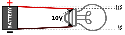
Any electrical conductor has a property called "electrical resistance". A consequence of this resistance is that when a current flows through the conductor, some voltage will be lost (i.e. converted into heat). Most people know from experience that the 12V of the battery "becomes somewhat less" at the end of the cable when a current is flowing through it. Many people however do not realize that this applies not only to the "plus" cable, but also to the "minus" cable.
The voltage at the end of the positive cable drops down and is "lower" than the 12V at the feed point.
The voltage at the end of the negative cable creeps up and is "higher" than the 0V at the feed point.
If this confuses you, just remember that the minus cables in your ship are not everywhere exactly 0V when current is flowing through them. If the end of the cable is attached to something which is connected to the seawater it will result in unintended impressed current cathodic protection, where the wrong object will be "protected" and the object at the end of the cable becomes the sacrificial anode.
Any minus/ground cable attached to something which is connected to the sea water should not be used to transfer electrical current for more than a few seconds! Always separate the grounding wire from the current transferring minus cable!
Alternator connected to the engine block
This is unfortunately a common situation. The engine block is for its electric starter already conveniently connected to the minus of the battery with a hefty minus cable, so why not use the same cable for the minus of the alternator? In fact, this is common practice with automobile engines, and since many marine engines are based on car engines chances are that your alternator is directly connected to the engine block or even doesn't have a minus connection but just uses its housing, which is bolted onto the engine, as its minus.
Catamarans
Let's see what the consequences are in a typical catamaran with two engines and non-isolated saildrives (like Yanmar). With just one engine running, one engine minus cable is conducting alternator current, the other one not. The one with the alternator running has inevitable cable losses, so the minus at the other end of the cable "creeps up". Any voltage loss will present itself as a differential voltage between the two engines. If the voltage loss is 0.2V, which can even be easily more if the alternator is running at full output, there will be 0.2V difference between the two engines and 0.2V difference between the two saildrives. The saildrive with the running engine will have a 0.2V lower voltage so the other saildrive starts to act as a sacrificial anode. This is a case of unintended impressed current cathodic protection. This explains the mystery why sometimes one saildrive/prop is eating through its anodes (or itself!) much faster than the other one.
Even with two engines running, it is unlikely that both saildrives will see the same voltage, as the output of both alternators will not be the same, the minus cables will not have the same length, etc. The only correct solution is to separate the current conducting alternator output from the ground cables which connects both engines together. This means that you should run a separate, dedicated minus cable from the alternator to the battery. Yes, it means you will have two big black cables between the battery and engine; one for the starter and one for the alternator.
For the same reason, always connect other power sources (like solar panels) directly to the battery and never via one of the engine minus cables.
Monohulls
Monohulls, although less susceptible, might have a similar problem when the minus of the battery is connected to other seawater immersed parts, or when a generator is used which shares its ground cable with that of the engine.
Shared minus cable of the anchor winch or bow thruster
The minus cable of the anchor winch or bow thruster is heavy and runs through the entire ship, so why not a make a joint somewhere to connect other devices? If the anchor winch is grounded to the minus cable (which should not be the case but have you checked that?), any voltage loss over this cable will present itself as a differential voltage between the anchor chain and engine/saildrive/prop combination, which invokes impressed current cathodic protection. Your anchor chain will become a sacrificial anode, it will quickly eat through its zinc layer and will start rusting quickly thereafter.
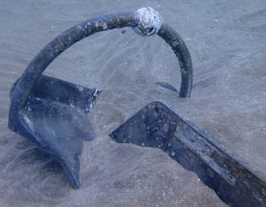
Is the rudder shaft really electrically neutral?
In a non-metal ship, the rudder shaft is typically not connected to an anode, but left "electrically floating". At least, that is what is intended. There are however numerous stories about rudder shafts that had completely corroded away, so this practice is somewhat flawed.
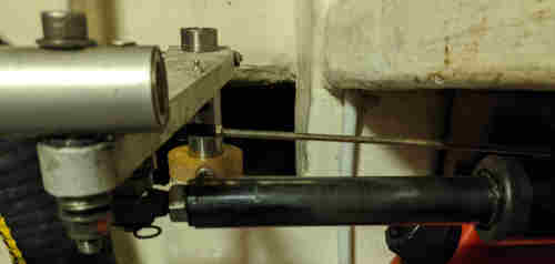
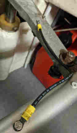
On ZwerfCat, I took a good look at the situation. The rudders are connected to control rod, and the port control rod is connected to a linear drive of the autopilot. Autopilots are typically somehow connected to the battery and if the drive rod is not isolated from its electrical motor, any voltage loss in the negative feed cable of the autopilot will present itself as a small positive voltage on the drive rod and thus also the rudder shaft, converting the latter into an unintended impressed current anode...
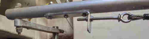
Also, the rudders are driven by a steel cable from the steering column. Is the steering column isolated? Will it remain isolated? Are we sure that in the future nobody is going to install a new VHF radio at the helm and connect its ground wire to the closest lump of metal which happens to be the steering column?
There are many, too many, opportunities for the rudder shaft to become somehow unintentionally connected to some electrical system and become an unintended impressed current anode. It would remain a disaster waiting to happen, we would have to monitor the rudder shafts continously. To reduce the chances of problems like this, I bridged all parts of the rudder linkage with some heavy cable and connected the main link rod directly to the big central anode. Now I only have to monitor this single anode but I have to monitor it anyway. It lasts a couple of years so that really cuts down on maintenance worries. An additional benefit is that the rudder shafts are no longer "floating" but protected by an anode instead.
Aluminium hulls
Our first boat "Omweg" was an aluminium ship, which was one of the reasons why I did some research on corrosion. It became quickly clear that there are just two rules to follow without any exceptions, and then the aluminium hull will last forever:
Do not connect any other "higher" metal to the hull
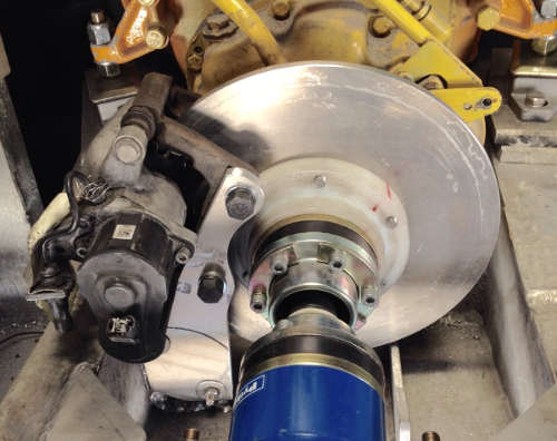
As we have seen in the hierarchical table aluminium will sacrifice itself for most other metals. So you should make sure any other metal that comes into contact with the seawater should be electrically isolated from the hull. This sounds easier than it is. It is pretty much unavoidable that the engine is connected to the hull, so we had to somehow electrically isolate the prop shaft from the engine. (See our prop shaft brake project).
We had a water-cooled fridge, so we had to use big plastic washers at the immersed condenser to isolate it from the hull.
Do not allow any stray currents
Preventing stray currents was the most challenging part. The basic rule is simple: Just act like if the boat is made from plastic and run a negative wire to every device and never ever connect something to the hull. Actually, this would be easier if the boat would indeed be made from plastic, but since it is from aluminium there are many caveats. A big one is the anchor winch. Since the anchor chain is a metal and immersed into seawater it should be isolated from the hull, also the tail of the chain which is still inside the boat. This also means that the entire anchor winch should not be in contact with the hull, or that the gypsy should be isolated from the winch housing.
Be particularly careful with radio's. The coax connector of the VHF radio is typically connected to the minus of the radio, and antenna mounting feet are usually also electrically connected to the coax connector. If you don't interrupt this path somehow, part of the current used to power the radio will finds its way via the coax cable to the mast and from there to the hull. Our solution was to use a half wave antenna (they don't need a "ground") and isolate the antenna mounting foot from the mast.
SSB radio's are even more challenging. Every antenna tuner will demand a solid ground connection, but this ground connection is internally connected to the minus... The solution is to install a special capacitor between the antenna tuner and the hull, which allows the RF energy to pass unhindered but blocks any DC voltages. Most people are unaware of this, so do your homework!
We rarely used shore power, but we had all sockets grounded to the hull and did never connect to the shore ground. Also, we used an isolation transformer between the boat and the shore grid. So actually we never had a galvanic connection with anything coming from shore.
During our time as owners of Omweg, we never saw any signs of corrosion of the hull.