Omweg has no steering wheel like you usually see on sailing yachts, but a tiller. There are pro's and con's on this, but that is outside the scope of this article. This article will show you how to boost your tiller pilot to achieve a reliable self steering.
The problem!
Because the majority of the larger sailing vessels have a steering wheel instead of a tiller, the manufacturers of tiller pilots assume that their product is going to be used on small light vessels. We bought the most powerful unit we could find but the tiller pilot is still way too weak. It can develop a force of only 85 kilo's and since it is mounted relatively close to the axle of the tiller, this power is not always sufficient. If a wave bumps against the rudder the poor tiller pilot has to absorb the full impact and when the boat luffs to windward due to a heavy gust both the range and power are insufficient to cope with it. Of course one should reef the sails but in that case it would be great if the tiller pilot could at least continue to do its job until reefing of the sails is accomplished.
During our Pacific passage we used our tiller pilot (a Simrad TP-32) a lot because we were sailing on a downwind track and after subtracting the boat speed there was insufficient air velocity left to keep the wind pilot working.
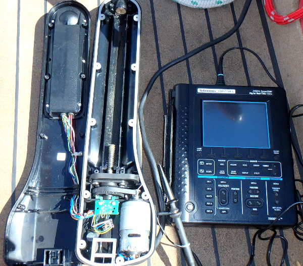
Unfortunately the tiller pilot gave up the ghost before we reached the Marquesas. Overloaded, worn out. The electronics worked still ok but the spindle was really worn out and just slipped. Fortunately we brought a spare tiller pilot with us but before we reached our destination also this unit developed a lot of play, the first sign of wearing down. These units costs about 750 US$ each so you won't want to bring a whole bunch of these things with you. We searched on internet for more powerful units but there are really not powerful enough units available, unless you start searching in the category "hydraulics", but then it is going to be a cumbersome, time consuming and expensive conversion. So it became necessary to create something myself...
Searching
The electronics of the defective tiller pilot was still working; actually I only needed an improved mechanic part, more specifically a "linear actuator". We had a small wish list:
- It should operate on 12 Volts. This is the voltage of our batteries and converting voltage in something else is inefficient.
- More power. Not just to solve the existing lack of mechanical power, but also because I would like to mount the unit closer to the rudder axle. Physics teaches us that when we halve the distance to the axle the required power doubles. And halving the distance was exactly what I would like to do because then I could mount the linear actuator against the rear bulkhead. Additional advantages would be that the required range and speed would also be half of what it otherwise would be.
- Sufficient range. We desired a larger range than we had with the old tiller pilot. But because the linear actuator was going to be mounted closer to the axle actually less rod extension would be sufficient. The tiller pilot had a range of 10 inches, so if the linear actuator would have a range of 6 inches then we would have exactly the desired rudder movement range.
- Sufficient speed. The tiller pilot was fast enough; we would like to keep approximately the same speed. But since the linear actuator was going to be mounted closer to the rudder axle half the speed would be exactly right.
- Power consumption. This is of course important because during sailing all our power has to come from solar panels and wind generator. Not even to mention that during the night the solar panels don't work. Every Amp would count.
- Spray water resistant. No further elaboration required I think.
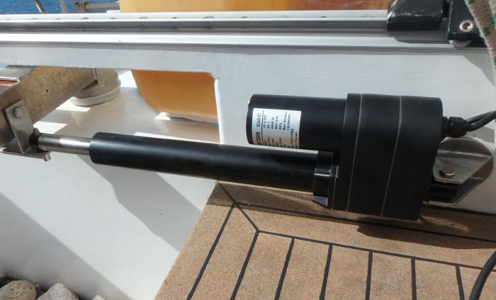
On www.servocity.com we finally found a suitable linear actuator in the category "super duty". A real beast which can push and pull 450 kilo's and can handle a static load of 3000 kilo's. Ha! Let these waves try to break that! Even after a correction factor because of mounting the linear actuator closer to the rudder axle the force would still be a factor 3 more than the force of the original tiller pilot. We could simply specify the required range when ordering, so it became 6 inches. The specified speed is only one third of the tiller pilot, but because it is going to be mounted closer to the rudder axle it would approximate the old speed good enough. And we are comparing the unloaded speeds, but since this linear actuator is so powerful it would probably not slow down as much under load as the tiller pilot so in the end it could turn out to be even faster than the tiller pilot. The required current was specified as 3 amps so with a estimated duty cycle of 10% the power consumption would be 300 milliamps. A whole night of autopiloting would then consume 4Ah and this would be 1% of our battery capacity which we consider acceptable. And it has a IP65 rating so it would be spray water proof. The price was only 400 US$ because it didn't specify "boat" in its application list. And you know that "boat" means "Bring Out Another Thousand"...
Mounting and connecting
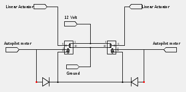
In our planned setup the old tiller pilot would drive the linear actuator. The electronics was still working ok just as its own little motor; only the spindle was worn out. But of course the tiller pilot was not designed to control anything else than its own internal motor. Some tinkering would be required but it isn't that hard if you have some knowledge about electronics. Of course it would be possible to connect the linear actuator in parallel to the motor of the tiller pilot but it could well be possible that this would overload the drive capacity of the tiller pilot's electronics. So I used two relais and two diodes and thus, depending on the rotation direction of the tiller pilot motor, only one of the relais would be activated at a time. This way of controlling the linear actuator also has the additional advantage that its motor is shorted out when there is no signal, so the motor becomes an electric brake and doesn't coast out after every drive pulse.
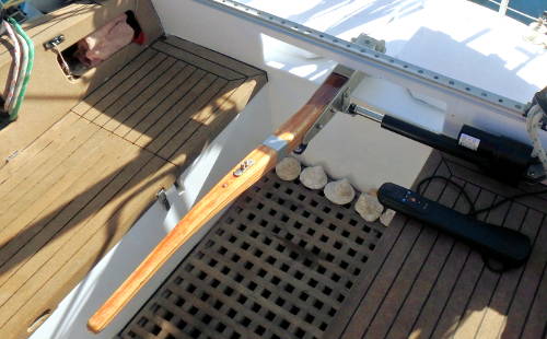
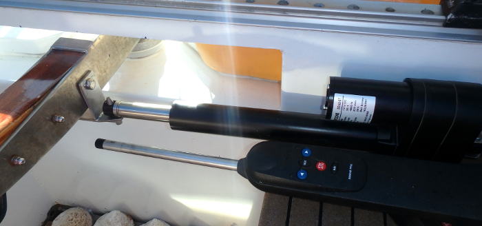
The mechanical connection to the bulkhead and rudder was a matter of thinking, measuring, thinking again, finally resulting in a drawing which was taken to a local welder who produced two nice stainless steel brackets.
The result
If we activate the linear actuator we can't keep the tiller from moving with all our force! So it has enough power to do its job. And controlling the linear actuator with the tiller pilot works like it was designed for this job. The only minor issue is that the tiller pilot has sensors which sense the rotation and direction of its internal motor, so we can't remove the further useless motor of the tiller pilot. If we cut the wire the brain gives an error signal and stops driving the linear actuator. We could probably fake the sensor signals with an Arduino, but of course at some point you need to question how far you should go with modifying an existing unit instead of just designing or buying a new control unit. The goal was to create a fast, efficient and not too expensive way to continue our circumnavigation with a much more reliable selfsteering device and we think we succeeded in doing this. Hopefully this article helps a few of you out there as well. We would like it if you let us know!

