We have created a computer controlled prop shaft brake out of affordable materials. In this article more about the why and how. For do-it-yourselfers we have added the schematic diagram and computer code near the bottom of this page.
Why?
The sub title of this article is: "Why and how?". For the "why" there are some reasons: a few no-brainers but also a few which are more difficult to explain.
Wear, noise and vibrations
A cruiser circumnavigating the world will experience more prop shaft rotations due to sailing than due to motoring. The bearings and gearbox will wear due to sailing, not due to motoring. The rotating drive train will produce vibrations and noise. Some brands of gearboxes have lubrication which is engine driven, a free wheeling prop will wear down the gearbox fast. Many gearbox manufacturers recommend to lock the prop by putting the gearbox in reverse.
Non static props
Folding props, Autoprops, Maxiprops, etc. reduce drag during sailing by taking the blades out of the stream or by feathering the blades. But this only works if the prop stops rotating. For these types of props the answer is clear: the prop has to be locked!
Drag
The question what produces more drag, a locked prop or a free wheeling prop, invites quite some discussions. Unnecessary because this question has already been answered many times by theory and practical tests. The only reason why this question pops up over and over again is that the answer is against intuition. You would expect that a free wheeling prop produces less drag, every counter answer raises suspicion and in addition the explanation is difficult to comprehend without sufficient knowledge about aerodynamics and fluid mechanics. As a pilot and airplane builder I have quite some knowledge about how propellers work, and about the procedures that need to be followed when an airplane or helicopter experiences an engine failure.
- To start with the last mentioned case: If a helicopter experiences an engine failure it can still make a safe landing, if the prop is allowed to free wheel. The prop will auto rotate without an engine because the airflow over the sinking helicopter will drive the prop. If you would lock the prop the helicopter would plunge to earth like a rock. What happens here is that the rotating blades produce drag, drag which is sufficiently high to prevent the helicopter from dropping down. Now rotate this picture by 90 degrees: the helicopter doesn't go down but moves horizontally, and the prop is no longer on top but on its rear. Our helicopter is now a boat, a boat which experiences considerable drag as long as the prop keeps rotating. That was a great thing for our helicopter, but less desirable in a sailing yacht.
- An airplane pilot learns during its course that during an engine failure it is important to stop the prop from rotating. The free wheeling prop produces a lot of drag which slows the airplane down, so the pilot has to maintain a steep glide angle to maintain a safe speed. If you pull up the airplane for a short moment so the speed drops off, the prop will stop rotating, and when picking up speed again the prop will likely remain stopped, giving the pilot a much longer glide path so he has more chances to find a suitable landing spot.
- In the case of multi engine propeller aircraft it is customary that the airplane manufacturer dictates that in case of engine failure the associated prop needs to be stopped, because a free wheeling prop produces so much drag that the airplane is flying skewed and can even become uncontrollable.
The science behind "air props" and "water props" is identical. In both cases they have an airfoil, a special shape that has special properties when the current not moves against but over its surface. An airplane wing changes from a piece of board to a shape which produces "lift", a prop (which is nothing more than a rotating wing) produces propulsion, or, if you reverse the situation, extra drag.
In theory the drag of a truly free wheeling prop is not so bad, but as soon as the rotation experiences any friction the prop starts to "labor" and begins to draw energy out of the forward movement. It is named "induced drag". In real life a prop always experiences friction, due to the bearings, couplings, the gearbox, etc. Energy is now being stolen from the forward motion of the ship, energy being converted in noise, vibrations, wear and heat. This drag is not insignificant but increases progressively: Tests reveal that the friction of the drive train increases the induced drag of the prop with a factor three!
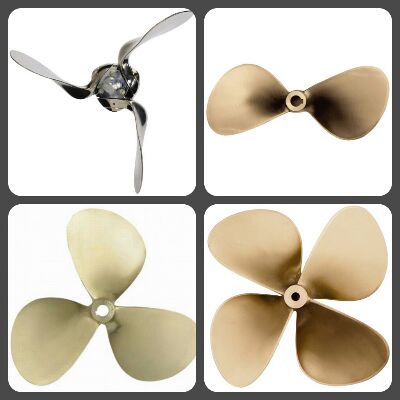
Although it is imperative that a free wheeling prop produces a lot of drag, the equation is only valid once we know how much drag a static prop produces. And this is where an airplane and helicopter differ from a ships prop: a static ships prop covers a much larger proportion of its working area than, for instance, the prop of a helicopter. So the theoretical "gain" by locking the prop becomes smaller when the static prop covers a larger volume of its working area. A fixed three blade prop produces less gain when being locked compared to a two blade prop. In the case of three blade props the free wheeling prop even produces less drag than the static prop... as long as you keep the friction out of the equation. This is often something which is "discovered" in not so well conducted tests, gets spread on the internet, and misleads lots of folks. Misleading indeed, because in reality the drive train of the prop produces so much drag that the supposed gain collapses into a loss. This is due to the fact that in the "test" nobody added the friction from the drive train and gearbox, which is unavoidable in real life. So in practice stopping the prop from rotating is always favorable considering drag. And then of course there were a few more good reasons to stop the prop...
But how?
Our original gearbox was a mechanical one. The prop shaft could be easily stopped from rotating by switching the gearbox into forward or reverse. But our new gearbox is a hydraulic gearbox... And if the engine is not running the hydraulics are not working and everything is free wheeling. Asking the manufacturer of our Autoprop about it he told us that the prop will only feather when the rotation stops. So we had to incorporate something to stop the prop from rotating: a prop shaft brake!
Disc brake
After some searching on the internet it became obvious that a disc brake would be the easiest way to brake the prop shaft. The question however was what we were going to use as brake caliper. It would be great if we could use a brake caliper which opens on hydraulic pressure, because then we could use the hydraulic pressure of the gearbox (or from the engine oil) to open the caliper automatically. But unfortunately normal calipers work just the other way around: pressure is used to close the caliper. Converting an existing caliper into reverse operation didn't look feasible, so we had to find another solution. Of course we could just use the caliper of a motorbike or something and mount the brake lever in the cockpit, lockable with an elastic band, but we didn't like that too much. And of course it is just waiting for the moment someone forgets to release the brake when starting the engine... and then something is going to break, but it is not yet clear what that "something" would be.
Electric caliper
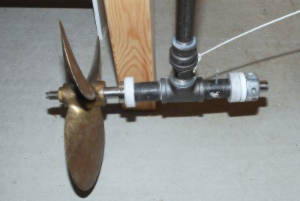
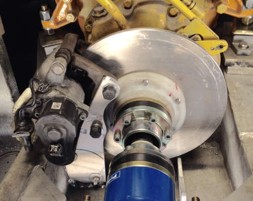
By coincidence someone told me that there are cars which have an electric parking brake. It didn't take long before I had found out which brand and models of cars have this kind of brakes and had obtained such a brake from eBay. The ship was still in repair at that moment, welding was being conducted, and the drive train was still in development. The addition of a brake disc could be integrated with the galvanic isolation between the propshaft and the engine. (Galvanic isolation with the prop shaft is required in an aluminum yacht, at least as long as you don't want the whole ship to act as an anode for the prop shaft and prop.)
The caliper could be easily opened and closed by applying 12 Volts over its connector, but it requires careful timing of breaking the electrical connection. In the associated cars this is handled by a computer which detects the increase in electrical current when the brake locks up and subsequently breaks the connection, but this computer most likely won't work outside of that particular car. So we had to choose to just use a switch and control the duration of the current ourselves (which equals to "guessing" when you don't have sight on the prop shaft), or to build some piece of electronics to deal with the procedure.
We thought the latter would be best, not just for convenience but also to prevent errors in operating the brake, in particular to prevent someone from forgetting to release the brake when starting the engine by just releasing the brake automatically as soon as the engine is switched on.
Computer controlled
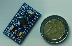
After considering various possibilities I chose for control by a small computer. This sounds like overkill and indeed it is... but because you can buy such a computer (Arduino pro mini) for just 2 Euro's and it hardly uses electrical power at all, I found it an attractive solution. Once you go this route you can do many nice things: making things configurable like braking power, opening time, you can let it automatically adjust for brake pad wear, etc.
Building
If you want to build a computer controlled prop shaft brake yourself, below you will find the details. Using my schematic and computer code for personal use is allowed, but for commercial application you will need my permission. The schematic and source code are copyrighted material. Using this idea and/or implementing my schematic or source code are for your own risk and responsibility: a locked brake failing to release can have dire consequences.
Don't like or not enough experience to solder or program yourself? Contact us; maybe we can supply you a fully working sample for an appropriate fee.
Operation
For the operation of the brake with the schematic and computer code below there are multiple options which can be selected by grounding specific pins of the Arduino.
For control of the brake we use a momentary toggle switch with neutral center. Pressing the upper half will lock the brake, pressing the lower half will release the brake. When the contact of the engine is engaged the brake is released automatically and can not be applied as long as the engine is running. The switch is equipped with an LED which indicates whether the brake is locked or released.
When the brake is held in the release position during powering up of the device, setup mode is selected. The brake will now be controlled without interference; the brake motor will keep running until the switch is released. The computer monitors the timing and current and records this for automatic operation of the brake. This way you can configure how much force the brake should apply when locking and how far the brake pads should be moved away when releasing. The interesting thing is that this way the computer will even deal with wearing brake pads and always lock the brake with the same force.
You will also find a programmed pin with the name OVERRIDE. When this pin is grounded then it becomes possible to operate the brake "manually" by keeping the switch pressed after the controller would normally stop the brake motor. We have used an additional switch (not incorporated in the schematic), mounted close to the brake itself. This switch is dual pole and operates the switch inputs as well as the OVERRIDE input. The idea here is that this switch can be used during maintenance of the brake or drive train.
Regarding the LED there are two possibilities: A simple "LED on is locked, LED off is unlocked" but also a mode where the LED is normally off but indicates the brake state when the toggle switch is pressed briefly. This mode, which can be selected by grounding the INDICATION_MODE to ground, has the advantage that you don't have to look to a lit LED all the time during sailing.
When the brake motor is running (during the transition of the brake state) the LED will flash rapidly so you have an indication that something is happening.
Hardware
The brake disc is made from a left over 8mm aluminum sheet which was used to built the new keels. Probably other materials could be used as well, or it is possible to use the disc from a car or motorbike. The electric caliper we used is from the rear brake of a car from the VAG-group. The one we used is from a Volkswagen Passat, but these brakes are also applied in the more expensive models Seat's and Audi's. These brakes are combination brakes which can be operated by hydraulics as well as electrical power. We don't use the hydraulic part for our application, so it doesn't matter if the hydraulics is defect and it may even help to obtain an affordable sample.
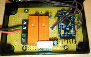
Electronics
To drive the brake we have used an Arduino Pro Mini on 5 Volts. Other models Arduino's should work too but you wouldn't gain anything by the extra's like USB-ports or more memory. An Arduino is not capable of delivering enough output to drive the brake directly, so you will need two relays and drivers for it. We also need a resistor to measure the motor current, a switch plus LED. We actually used ourselves two switches: one in the cockpit on the motor panel, and one in the engine room close to the brake. The latter is a double pole switch which also operates the OVERRIDE input on the Arduino. This facilitates testing and maintenance of the brake and drive train.
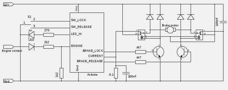
The pins of the Arduino depends on the model Arduino you use. In our source code the actual ports are declared and can be easily changed if necessary. The diodes are generic: I used 1N4148's. The transistors are generic as well: I used BC547's for this task. For the relays we need 12 Volt versions, capable of switching at least 8 Amps.
Software
To program the Arduino you will need, depending of the model Arduino, an external programmer. The Arduino Pro Mini we used needs an external programmer, but it is commonly available, with the same size and costs of the Arduino itself. And of course you will need the source code: Download the source code here.
The source code is commented so you can easily adapt it to your own needs. But only start doing this once you have confirmed that your combination of electronics and software actually works.
Hints
Some hints for building and usage:
- The current determines how forceful the brake is applied. The current can be configured in the setup mode. Don't let the brake apply more force than is actually needed to stop the prop shaft from rotating! In case the brake fails to release for whatever reason, it should be possible to run the engine through it or somehow force the caliper from the disc.
- Release the brake when the ship is in the marina. If the caliper seizes it is better to have this happening in the "open" position!
- Use good quality relays! A seized relay can have dire consequences like a burned out brake motor.
- Make sure the wiring from the brake to the control unit can be easily detached. In case of a defect control unit you will then have the possibility to connect the brake directly to the battery and to release the brake.

